Installation
Tools Required
- Screwdriver (for mounting bracket, if applicable)
- Wire stripper / crimping tool
- Cable ties
- Multimeter (for verifying wiring)
Mounting
- Select a mounting location that is:
- Protected from direct water exposure
- Away from sources of excessive heat (> 70 °C ambient)
- Secure the device using the mounting hardware or the cable ties.
- Ensure enough clearance for harness routing and service access.
Wiring
Power
Connect the device to a switched or permanent 12 V / 24 V DC supply from the vehicle harness. Refer to the pinout diagram in the Inputs/Outputs section.
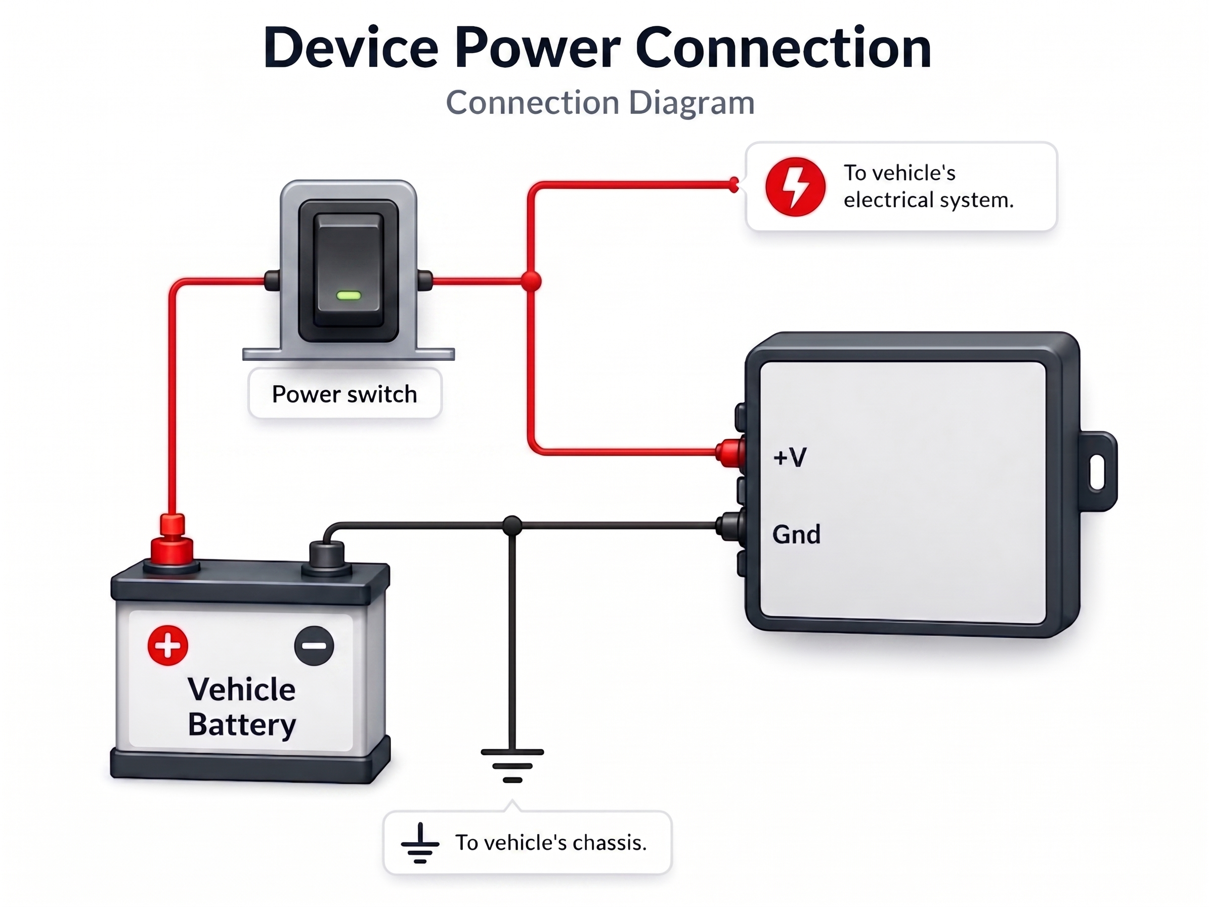
If the vehicle uses a main battery switch, either of these options can be used:
- Connect before the main switch (device remains powered when the switch is OFF).
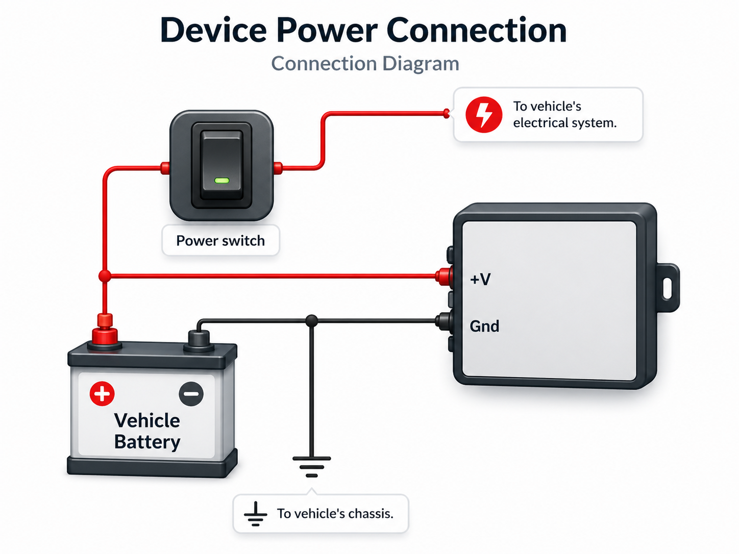
- Connect after the main switch (device turns off with the main switch).
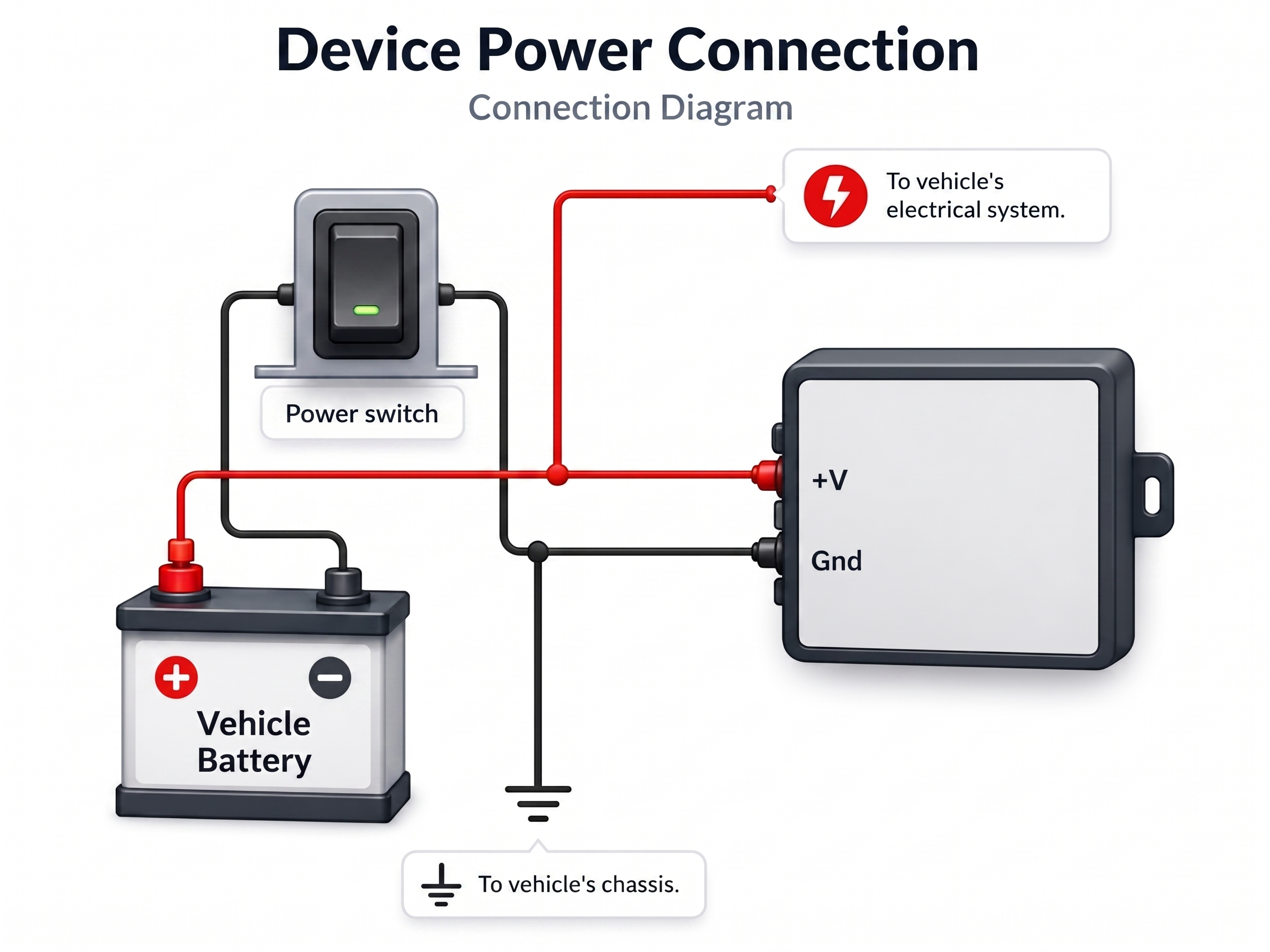
Use a fused connection (3 A recommended) to protect both the vehicle harness and the device.
Digital Input (IP1)
The most common use of IP1 is a panic button:
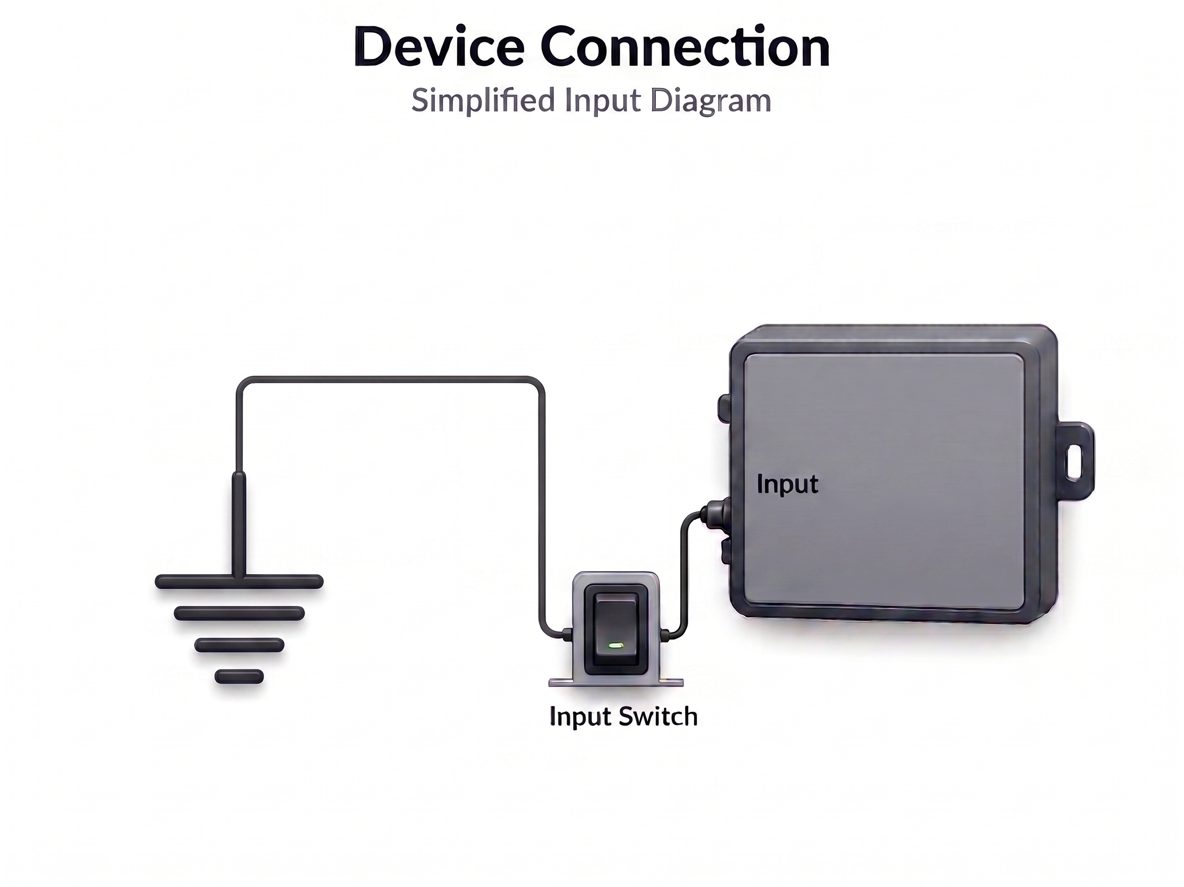
Electrical states:
| Logical State | Electrical State |
|---|---|
| Active | 0V to 2V |
| Inactive | 2.5V to 30V or open |
Adjust your event equation accordingly. Many installations wire IP1 to a 0 V active-low button.
Digital Outputs (XP1 / XP2)
The outputs are open-collector. Connect the load between the output and the supply voltage:
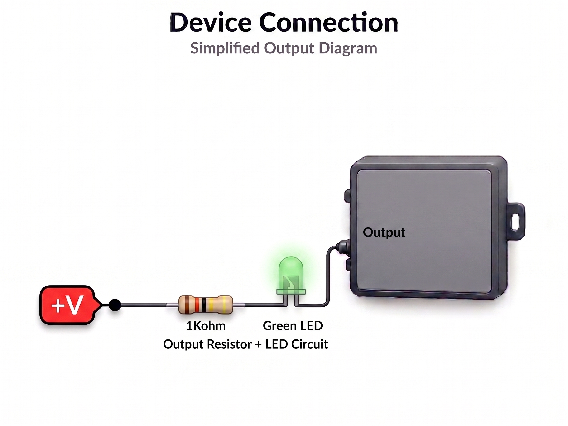
Maximum output current: see Specifications. Do not exceed rated limits. Outputs are protected against over-temperature (165 °C cutoff).
Initial Configuration
After installation, connect to the device via:
- TCP socket
- RS-232 serial port — At 115200 8n1.
Verify the installation with:
>QVR<          ← Query firmware version
>QST<          ← Query GNSS status
>QXANS<        ← Query network status
See Getting Started for a complete first-time setup guide.